Getting Started with Relyence RBD
If you would like to review a video overview of this Getting Started Guide, go to our online videos for Relyence RBD.
1. Sign in to Relyence
To begin, make sure you are signed in to Relyence. For details on signing in, see Signing in and Signing out.
You must have a Relyence account to sign in to Relyence. If you do not yet have a Relyence account, you can register for one for free.
You may possibly see the Announcements dialog when first signing into Relyence. The Announcements automatically scroll, or you can review them using the previous and next arrow keys. For any Announcements you do not wish to see again, select the Don't show me this again checkbox. Once you have reviewed all the Announcements, click the 'x' (Close) button in the upper right corner of the Announcements dialog.
2. Open the Example Analysis
First, let's make sure Relyence RBD is active.
After you have signed in, you may see a Welcome dialog. If a Welcome dialog does not appear, click Welcome to Relyence from the Help dropdown menu in the upper right of the Relyence header bar.
If you were previously working on an Analysis, you will see the Continue Where I Left Off option at the top of this dialog, otherwise it will not appear. If you are using a Trial version, the Show this page when Relyence opens option will not appear. This option is only available using a licensed version of Relyence.
Click the RBD tab on the left to activate Relyence RBD. Then click Open Example Analysis.
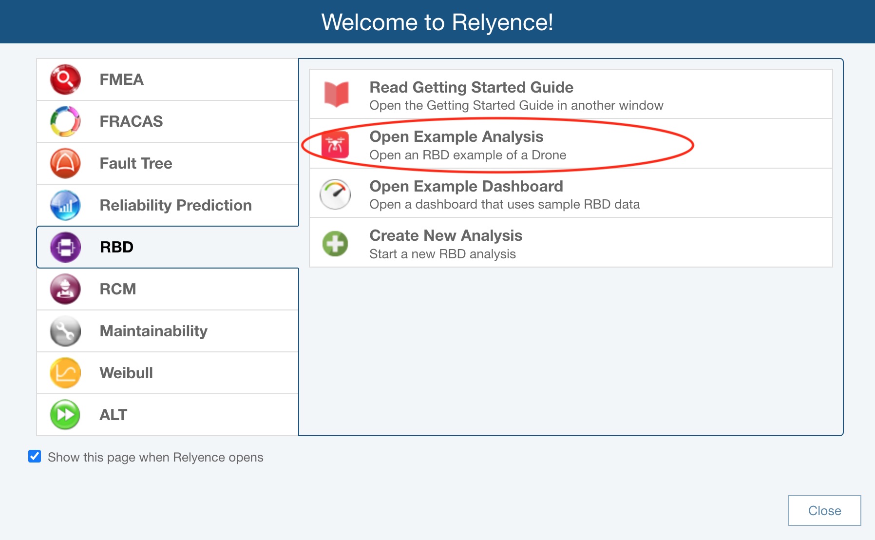
For this tutorial, we will use the Drone Example supplied with Relyence RBD.
When you open an Example, you will see the Revert Example pop up appear. You are free to make changes and save your changes to the Example Analyses. If you want to revert to the original Example at any time, click Revert Example. You will get a message asking if you are sure before your changes are discarded. Click Got it! to dismiss the pop up.
For this tutorial, we assume an unmodified original Example is being used. If you are not sure if you are using an unmodified version of the Example, click Revert Example from the Sidebar. You will be asked if you want to lose your changes and reopen the Example in its original version. Click Yes.
If you continue with a modified version, just be aware that screen shots or other functions may not operate exactly as described in this tutorial.
When complete, your Drone Example with its data will appear in the main window.
3. Review the RBD, Properties, All RBDs and RBD Plot panes
In the large window in the center when the RBD tab is selected is the RBD pane. This shows your reliability block diagram.
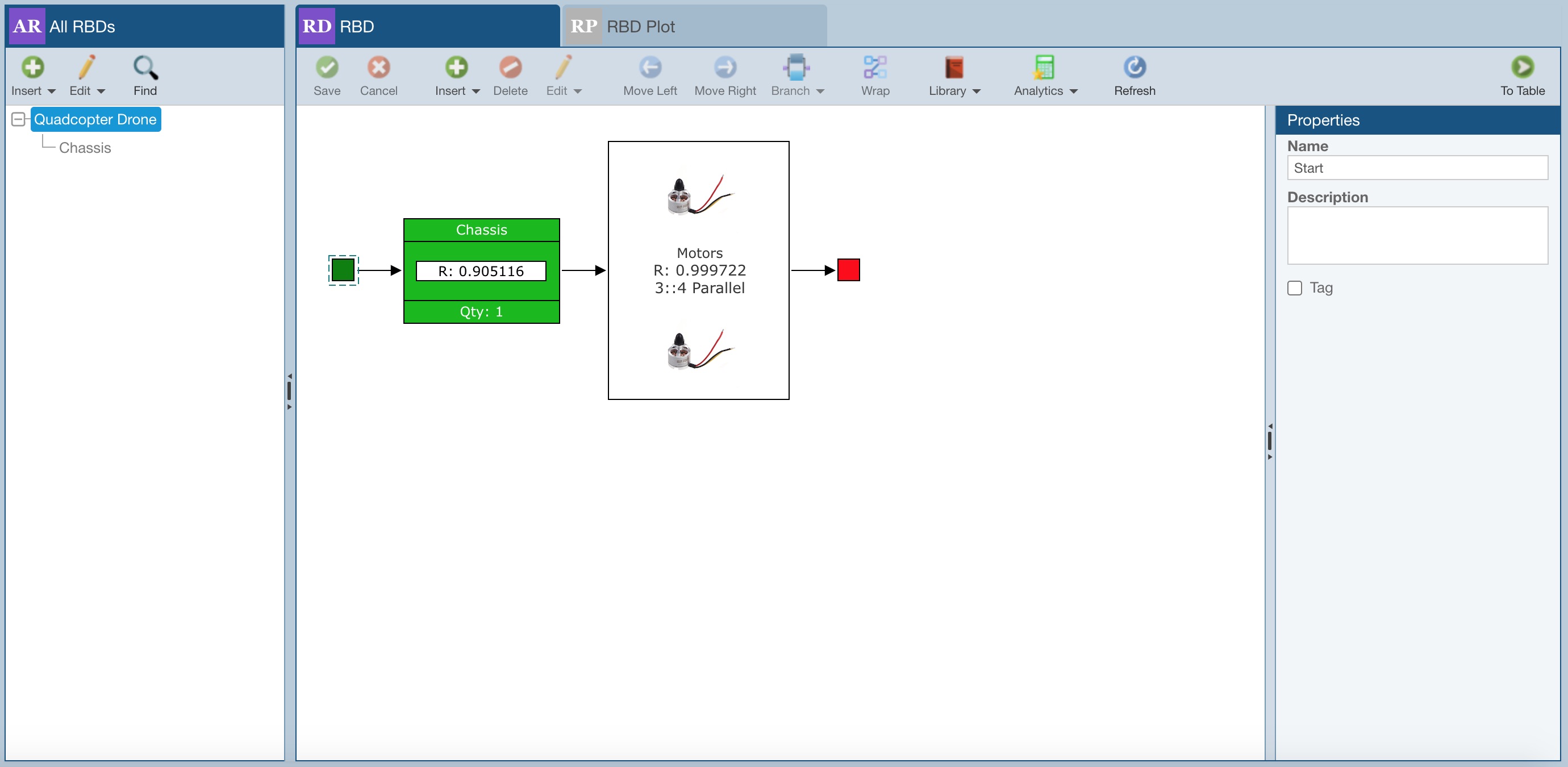
Select blocks in the diagram by clicking on them. As you select the various blocks, notice how the data associated with that block is displayed in the Properties pane on the right.
The two unique, smaller blocks at the ends of the RBD are the Start and End blocks respectively. The Start Block is green and the End Block is red. These two blocks cannot be modified, and are used to indicate the starting point and ending point of a successful path through your RBD.
Click on the block named "Motors" and notice the Properties associated with this block. "Motors" is a block that accounts for redundancy, so its Properties are different than non-redundant blocks, and includes more information.
.png)
The leftmost pane, All RBDs, displays a list of all your RBDs. RBDs may be linked to other RBDs through the use of Subdiagrams. Subdiagrams enable you to nest RBDs to make your diagrams easier to organize and maintain. The use of Subdiagrams also enables you to reuse RBDs across diagrams. So, you can define a single RBD, then link it as a Subdiagram to more than one parent RBD. The All RBDs pane displays the relationships between diagrams and subdiagrams and can be used to navigate through your diagrams.
In this Example, there is one subdiagram. In the All RBDs pane, click "Chassis" to view the subdiagram in this Example. Or, you can keep the Quadcopter Drone diagram selected, and navigate to the "Chassis" by clicking the Chassis block in the diagram and clicking the Go to Chassis link that appears in the Properties pane. You can navigate through your subdiagrams using the All RBDs pane, or the links in the Properties pane, as you prefer.
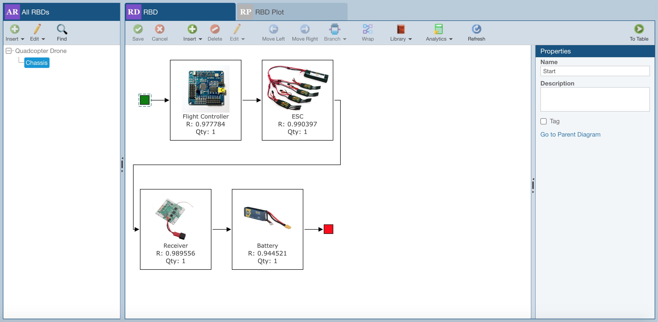
Click the Go to Parent Diagram in the Properties pane to go back to the main RBD.
Lastly, click the RBD Plot tab.
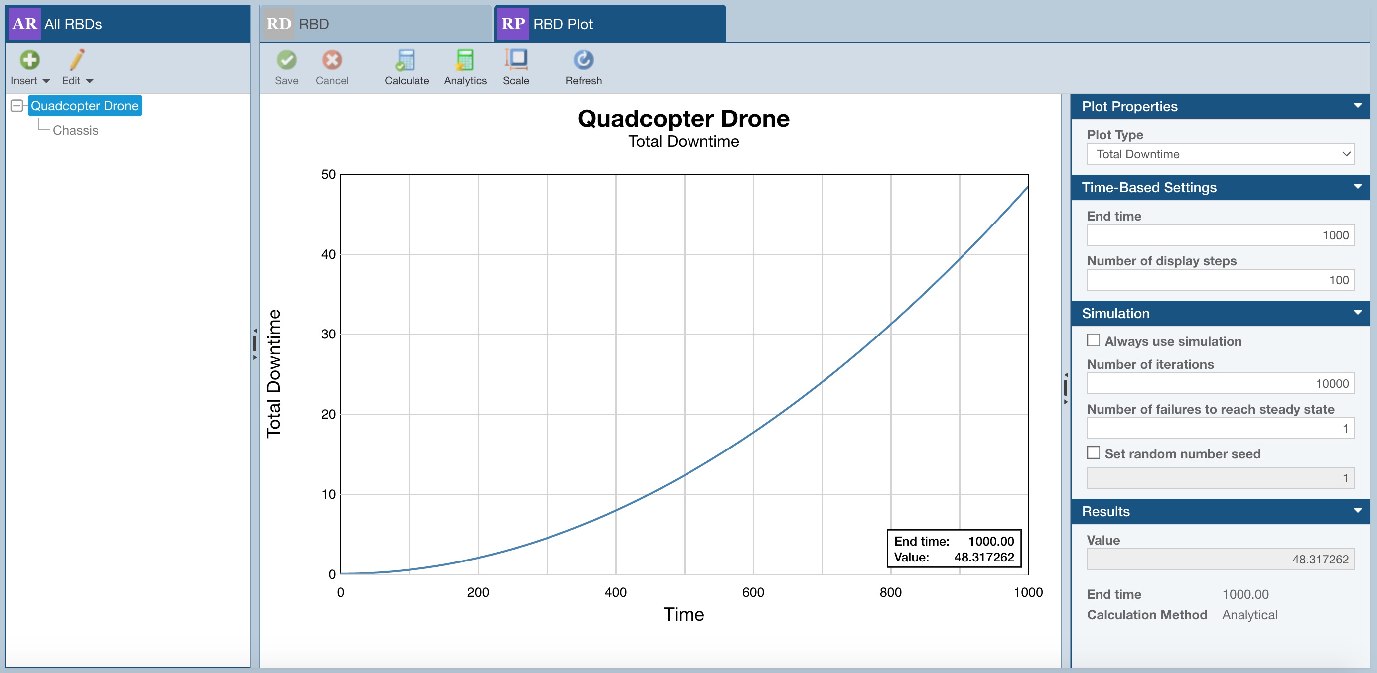
On the RBD Plot tab, for the RBD selected in the All RBDs pane, you can review various Plot Types, for which you set your preferred calculation settings, and also calculate additional metrics via the Analytics calculator. For more details, see Generating RBD Plots.
When you are done viewing the RBD Plot pane, click the RBD tab to return to the RBD diagram.
4. Calculate
Once you have completed building your RBD, you perform a calculation to see the results you desire.
If needed, in the All RBDs pane, click to select "Quadcopter Drone" and click to select the RBD tab.
To calculate results for this RBD, click Calculate from the Sidebar. The Calculate RBD dialog appears.
There are various options available for RBD calculations. For more information on these options, refer to the Performing RBD Calculations section. For now, make sure these selections are set for this calculation:
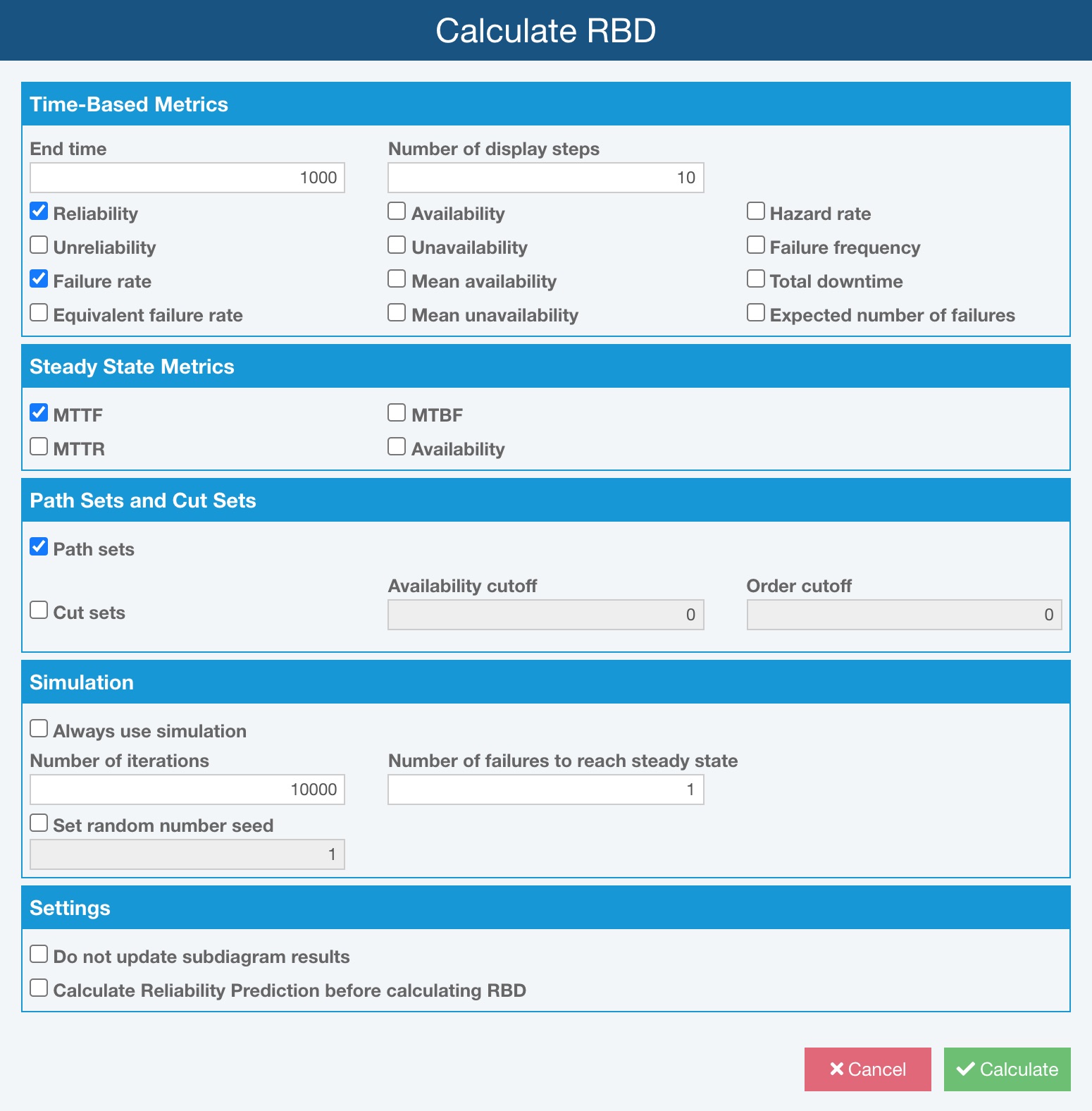
Click Calculate to start the RBD calculations.
The Calculation Progress dialog appears and the progress bar indicates calculation progress. Once the calculation is complete, the Results dialog displays.
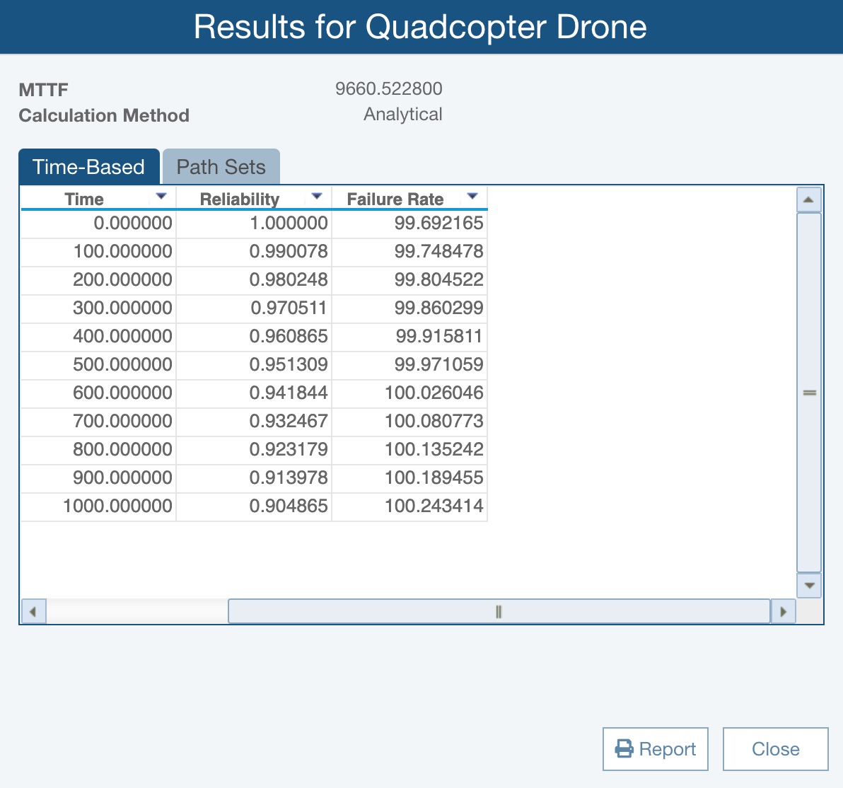
The Results dialog shows the overall results for your RBD. You can also view the individual block results for each block in your RBD. To do this, drag the Results dialog over until you can see the "Motors" block. Click on the "Motors" block to see the Results dialog update and display the calculated results for the Motors. To view the overall RBD results, select the Start or End Block.
Click Close when you have completed viewing the calculation results. Also, the Reliability of each of the blocks (at the specified end time point) will be shown on all the blocks of your RBD. The result value displayed on the RBD blocks can be set using RBD Properties, and is set to Reliability by default.
Anytime you want to view the Results again, click View Results from the Sidebar to re-display the Results dialog.
5. Report
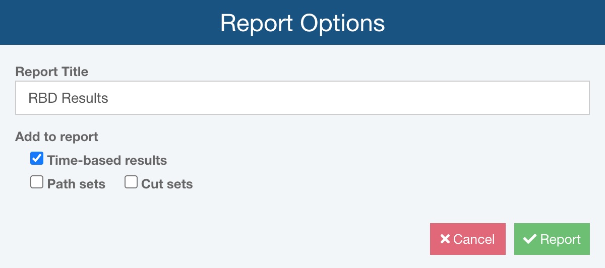
To generate a report of your RBD, make sure the RBD pane is selected and click Report from the Sidebar. The Report Options dialog appears.
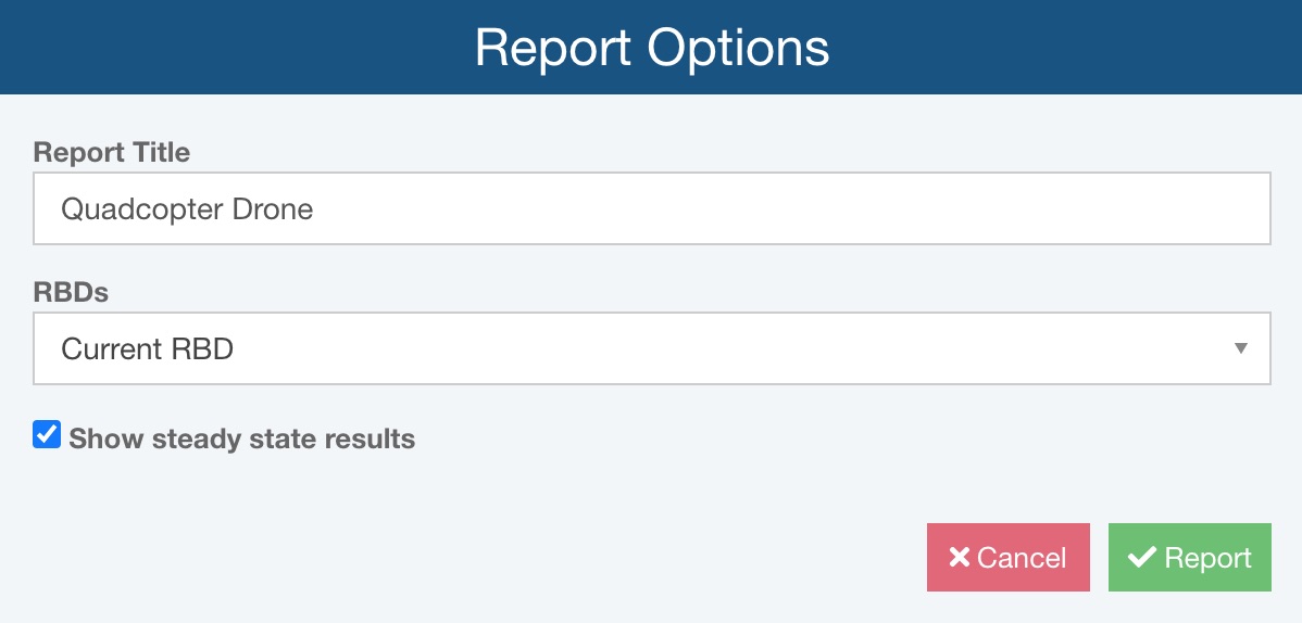
Enter "Quadcopter Drone" for the Report Title.
Select Current RBD for RBDs to include on the report.
Select Show steady state results to include the RBD steady state results at the top of the report.
Click Report to generate your RBD report.
The report appears in a new browser tab.
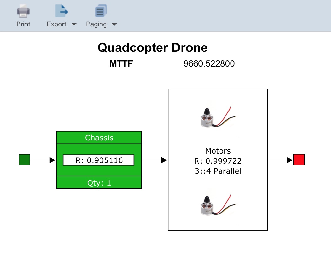
You can print your report by clicking the Print button in the toolbar. You can choose to export the report to a JPG, BMP, PNG, or SVG format if you would like. Select the appropriate graphical format from the Export dropdown in the toolbar. Note that you can also choose various options from the Paging dropdown.
Close the Report browser tab when you are done viewing the report.
You can also generate a report on the calculation results. Click View Results from the Sidebar, and then click the Report button. The Report Options dialog appears. You can enter the Report Title for your report. Select Time-based results and clear Path sets and Cut sets.
Click Report to generate a text-based report of your RBD results.
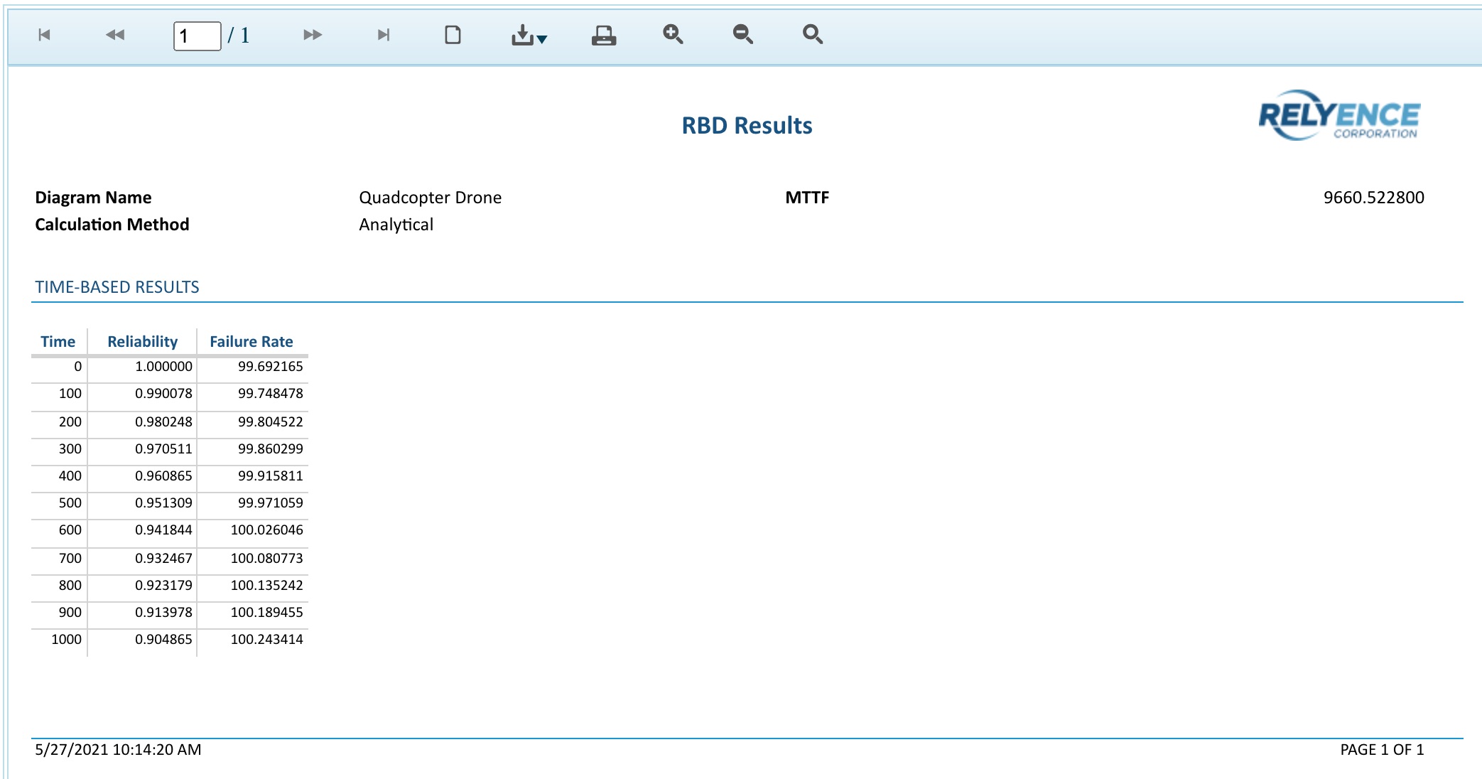
You can print the report, or save it in a PDF, Excel, PowerPoint, TIFF, or Word format.
Close the report browser tab when you are done viewing the report.
Click Close to close the Results dialog.
6. Add a new Block
We are now going to add another block to our Drone Example RBD.
Make sure that "Chassis" is selected in the All RBDs pane and the Chassis RBD is displayed in the RBD pane. Click on the "Battery" block to select it.
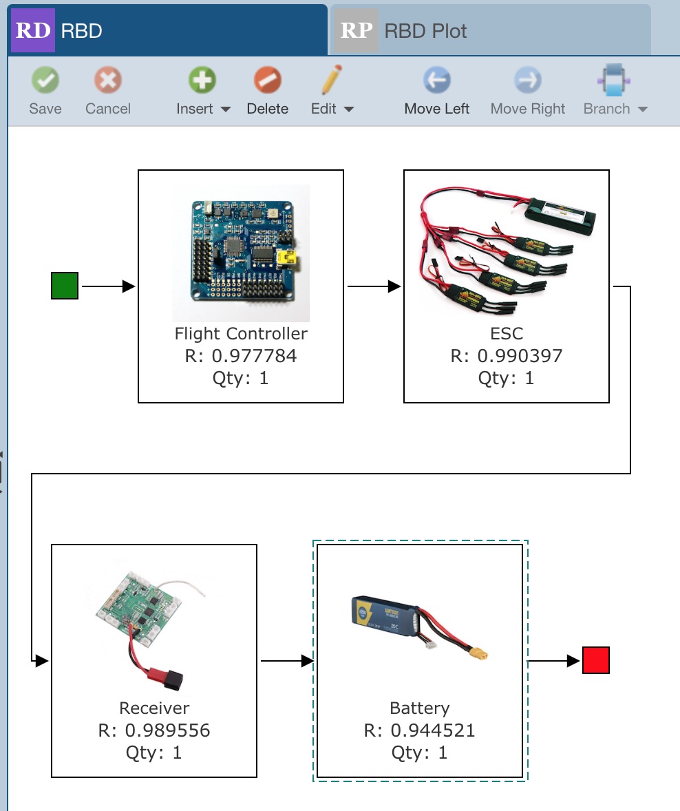
From the toolbar, click the dropdown arrow next to Insert. The list allows you to select to insert a single block, redundant block, a subdiagram, a repeated block, a branch, a block from a library, or a subdiagram from a library. For this example, we are going to insert a single additional block for the GPS. For more information building your RBD, refer to the Building your RBD topic. Select Insert>Block to insert a new block after the Battery.

The newly inserted block is automatically selected for you.
RBD includes the ability to auto-wrap so you can control the layout of your diagram. With the newly inserted block selected, click Wrap from the toolbar. Relyence RBD will automatically layout your diagram with the new block below the current blocks and connected correctly.
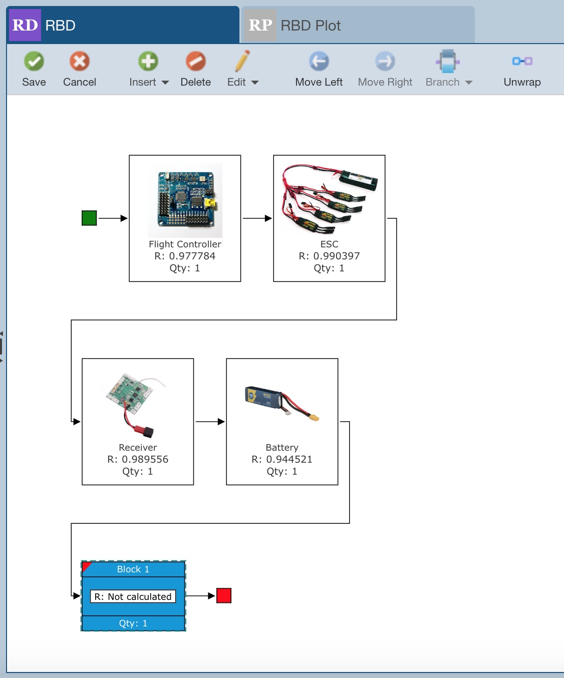
Now, click Unwrap to move the block back to its original in-line location. The wrap feature of RBD allows you to effectively manage your RBD layout. The layout of your RBD on your display also controls how your RBD will appear when printed.
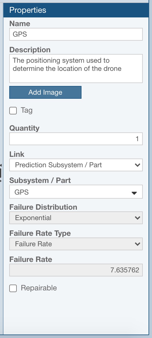
We now want to enter the Properties for this new block. Enter "GPS" for the Name of this block, and "The positioning system used to determine the location of the drone." for the Description. Below the Description, the Add Image button allows you to add an image if you would like. The Tag checkbox is a special indicator field you can use for any purpose you desire.
The following set of fields are used to define the characteristics of this block that will enable the calculation engine to model the block in order to evaluate overall RBD metrics.
Quantity: enter the number of units of this block that are present in your system. For our Drone Example, we have 4 motors, so the quantity of 4 for the Motors block is noted in our parent diagram. For our new GPS block, leave the quantity at the default value of 1.
Redundancy Type: (hidden for this block) select the type of redundancy, if employed, for this block. When the quantity is set to 1, there can be no redundancy, so this selection is hidden. If you enter a quantity greater than 1, you can select from the list of Series, Standby - Cold, Standby - Hot, and Parallel redundancy types.
The following fields do not appear in this example because there is no redundancy with our GPS. If a Redundancy Type other than Series is selected for a block, the following additional fields will appear:
- Quantity Required: If you select a non-series redundancy, the Quantity Required field will be shown for you to enter the quantity of units required for operation. For example, you may have 2 of the same units in a redundant configuration, but one is off and in standby mode and only turned on when the first unit fails. In this case, the Quantity would be 2, but the Quantity Required is 1.
- Switch Probability: If you select a non-series redundancy, the Switch Probability field will be shown for you to enter the likelihood the switchover to use a redundant component upon failure will be successful. You can enter a value from 0 - 1. A "0" indicates the switch will always fail, a "1" indicates the switch will never fail. The default is 1.
- Switch Delay (Minutes): If you select a Standby redundancy, the Switch Delay field will be shown for you to enter the switch delay time. The delay time is the number of minutes it will take to switch over to a backup unit upon failure in a standby redundant configuration. The default is 0.
Link and associated parameters: The Link function allows you to link this block to either another Subdiagram, or Prediction Subsystem or Part, or Weibull Data Set. If you choose to link to another subdiagram, you will need to select the Subdiagram you want to link to. If you choose to link to a prediction subsystem or part, you will need to select the Prediction Subsystem/Part from Reliability Prediction to link to. If you choose to link to a Weibull Data Set, you will need to select the Weibull Data Set to link to. In any of these cases, the results for this block will obtain the characteristics for modeling from the underlying linkage. In this case, our GPS is modeled in our Drone Example in Reliability Prediction. Select "Prediction Subsystem/Part" from the Link dropdown list. Click the dropdown list for the Subsystem/Part field to view your Analysis Tree hierarchy. Expand the Motherboard assembly and select the "GPS" for the Subsystem/Part. Once selected, you will see the associated failure parameter data appear. By default, Relyence RBD will use the calculated predicted Failure Rate from Reliability Prediction as the Failure Rate for this block. If you wish to use a different value from the Reliability Prediction as the Failure Rate for linked RBD blocks, you can change this in the Analysis Properties. See Analysis Properties for more details. You will also notice that the RBD block changes to a green color from blue. Any blocks in your diagram that are linked in any way are shown in green to distinguish them from unlinked blocks.
Failure Distribution and associated parameters: If unlinked, you must enter the failure characteristics of the block. The failure parameters consist of the Failure Distribution and the corresponding distribution parameters. For more information about the failure distributions and the associated parameters, refer to the Failure and Repair Distributions topic. Because we are linking to the GPS in our Reliability Prediction, these fields are disabled.
Repairable: If this component can be repaired, select the Repairable checkbox. For this example, leave the Repairable checkbox clear.
Repair Distribution and associated parameters: If the component is marked as Repairable, the Repair Distribution and corresponding distribution parameters must be entered. For more information on repair distributions and their associated parameters, refer to the Failure and Repair Distributions topic.
Now you will need to save changes you made. Notice the red tag marks appear in the upper left corner of the newly entered block to indicate that unsaved data is present. Click Save in the toolbar. The newly entered block and its associated Properties are saved, and you will notice the red tag mark no longer appears.
If you would like, you can recalculate and generate a report with your newly entered RBD block. To recalculate the Chassis subdiagram, remain in this view. To recalculate the entire Drone, select the Quadcopter Drone to return to the top-level.
7. Moving On
Congratulations! You have successfully completed the Relyence RBD Getting Started tutorial! You are ready to move on!
You are welcome to continue using the Drone Example to try out some other features and functions or start with a new Analysis. To create a new Analysis, click on Drone Example on the Sidebar menu, and then click Create New... on the submenu, or select Welcome to Relyence from the Help dropdown menu and click Create New Analysis. Remember that you can also click Revert Example to start over with an original Example.
Please note that there are limitations in the Trial version in the amount of data that can be entered. You will be notified when you have reached these limits.
There are additional features not covered in the Getting Started tutorial, such as more information on using redundant blocks, branching, and calculation options. For more information on these features, go to Relyence RBD Advanced Features.