Configuring Boundary Diagram Interfaces and Blocks
The Boundary Diagram Editor is used to create and edit Boundary Diagrams used to define the scope of work for DFMEA in Relyence FMEA.
By default Relyence FMEA supplies 5 types of Interfaces that can be included in any Boundary Diagram. They include:
- Data Exchange - used to represent information exchange between blocks. Examples include: electrical signals, wiring harnesses, various computer inputs/outputs, and the interaction between a TV and remote control.
- Energy Transfer - used to represent the transfer of energy from one block to another. Examples include friction or motion transfer (such as with gears) and heat transfer, such as that between a CPU and a heat sink.
- Human-Machine - used to represent the interaction between a human and a device. Examples of systems that include Human-Machine interfaces are vehicles (gas and brake pedals), computers (keyboard and mouse), and many devices with manual switches.
- Material Exchange - used to represent the exchange of any type of material from one block to another. An example is the flow of gasoline from vehicle gas tank to combustion engine.
- Physical Connection - used to represent blocks that are physically connected such as blocks that are clamped, bolted, or welded together.
Note that default Relyence Interface types can be customized or deleted. Custom Interface types can also be added.
By default Relyence FMEA supplies 6 types of Blocks that can be included in any Boundary Diagram. They include:
- Analysis Tree Subsystem - represent the major elements of the system in focus and are subsystems or components defined in the Analysis Tree.
- Boundary - generally a dashed line rectangle that defines the scope for the DFMEA within the boundary; blocks within the boundary are under control of the Analysis team.
- External Factor - represent external elements whose interactions with other diagram elements should be considered; examples include environmental effects such as wind, temperature and humidity, as well as customer usage.
- Legend - optional element that can be displayed to provide a key for all configured Interfaces.
- Other Subsystem - represents a subsystem that is not within the scope of the analysis but whose interactions with other diagram elements should be considered.
- Text - can be used to include titles or notes on any Boundary Diagram.
Note that default Relyence Block types cannot be deleted, but their properties can be customized as needed.
In order to configure Interfaces and/or Blocks for your DFMEA Boundary Diagrams, from the Sidebar menu, click Configure>FMEA>Boundary Diagrams.

The Boundary Diagrams dialog appears.
.jpg)
On the Interfaces tab, you can see the Relyence-supplied Interfaces as well as any other interfaces that have been configured.
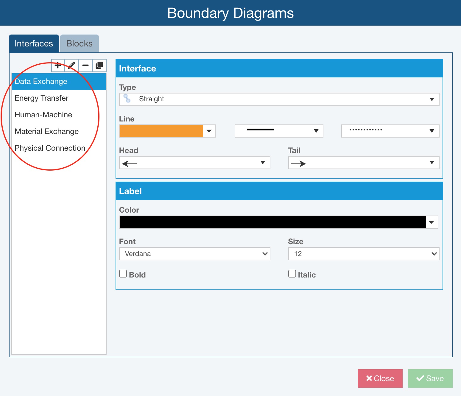
You can use the toolbar buttons on the top left and properties settings on the right to review, add new, or customize existing Interfaces.
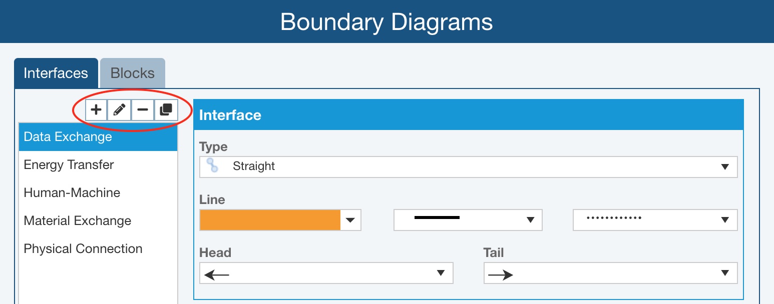
- Add - click the Add button to define a new Interface type. The Add Interface dialog appears where you can give the Interface a Name and then you can establish the properties of the Interface in the Interface and Label sections on the right.
- Edit - select any Interface and click the Edit button to provide a new Name for the Interface on the Edit Interface dialog. Adjust the properties of the Interface in the Interface and Label sections on the right, if needed.
- Delete - select any Interface and click the Delete button to remove that Interface type and confirm by clicking Yes on the Delete dialog. Note that if all Relyence-supplied Interfaces are deleted and no custom Interfaces are added, upon return to the Boundary Diagrams window, the Relyence-supplied defaults will be provided.
- Copy - select any Interface and click the Copy button to define a new Interface type that starts with the properties of the copied Interface. The new Interface will be given a unique name, which can be customized using the Edit button as needed. Properties of the new Interface can be set using the Interface and Label sections on the right.
On the Blocks tab, you can see the Relyence-supplied Blocks as well as any other blocks that have been configured.
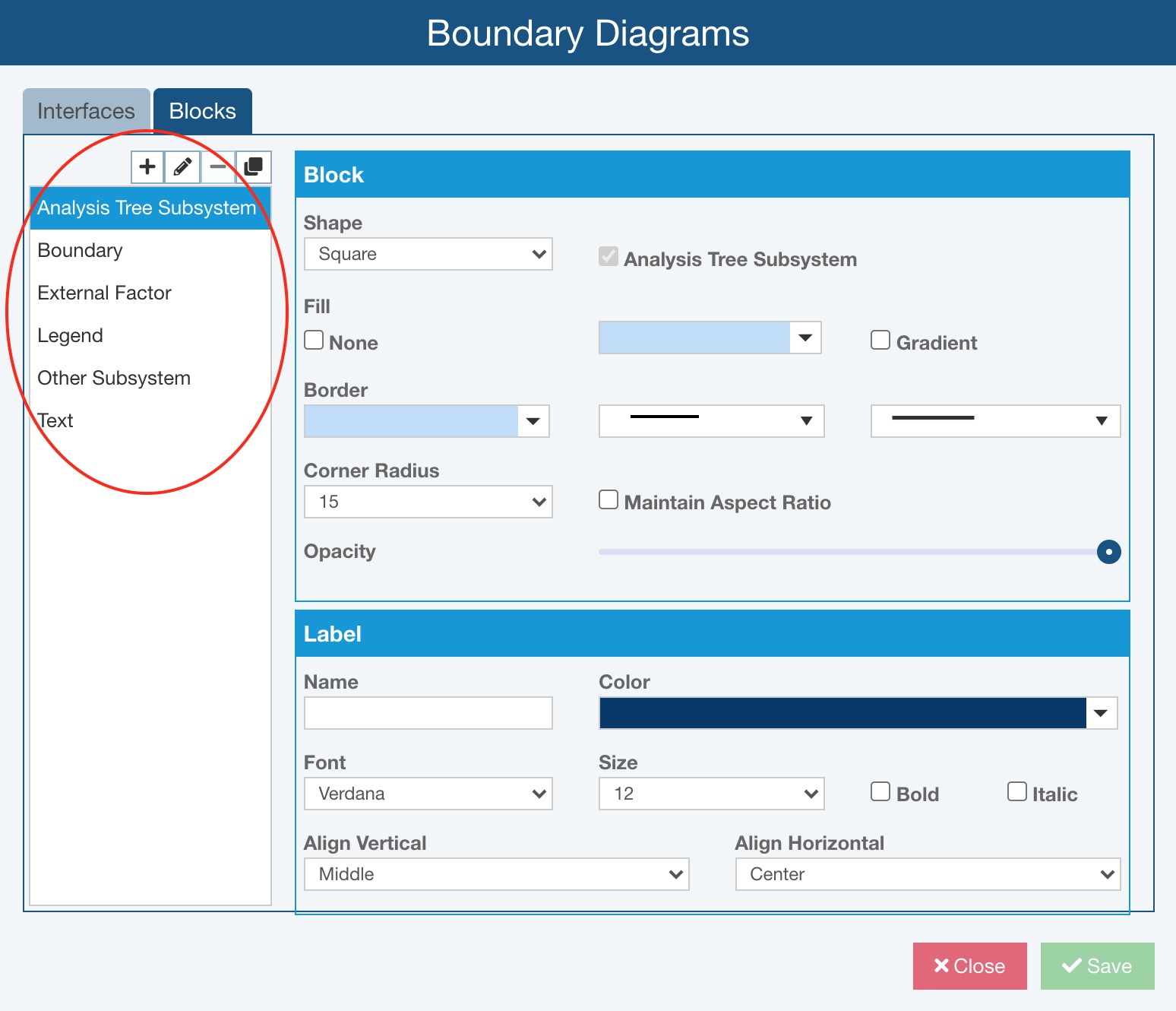
You can use the toolbar buttons on the top left and properties settings on the right to review, add new, or customize existing Blocks.
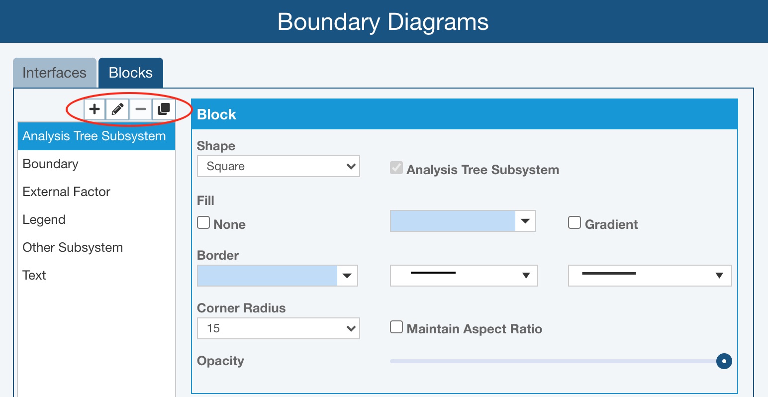
- Add - click the Add button to define a new Block type. The Add Block dialog appears where you can give the Block a Name and then you can establish the properties of the Block in the Block and Label sections on the right.
- Edit - select any Block and click the Edit button to provide a new Name for the Block on the Edit Block dialog. Adjust the properties of the Block in the Block and Label sections on the right, if needed.
- Delete - select any custom Block you have added and click the Delete button to remove that Block type and confirm by clicking Yes on the Delete dialog. Note that Relyence-supplied Blocks cannot be deleted.
- Copy - select any Block and click the Copy button to define a new Block type that starts with the properties of the copied Block. The new Block will be given a unique name, which can be customized using the Edit button as needed. Properties of the new Block can be set using the Block and Label sections on the right.
When you have finished reviewing and/or customizing the Interfaces and Blocks, click Close and choose whether or not to discard changes or click Save and then Close to return to the Analysis.
All Interface and Block types defined will be available for use on any DFMEA Boundary Diagram when working in the Boundary Diagram Editor.