Process Flow Table and Diagram
PFMEAs often begin with the creation of a Process Flow Diagram (PFD). The PFD describes your process in a detailed step-by-step manner. Developing a well-defined PFD is the basis for comprehensive and effective PFMEAs.
The PFD defines what product requirements, or characteristics, your process affects and how those characteristics are controlled to ensure that product requirements are met. The product characteristics are the outputs of your process, and the controls are the inputs used to maintain quality.
In Relyence FMEA, you can enter your process flow information using the Process Flow Table (PFT) view or in the Process Flow Diagram (PFD) view. Or, you can use both in conjunction to create your process flow diagram.
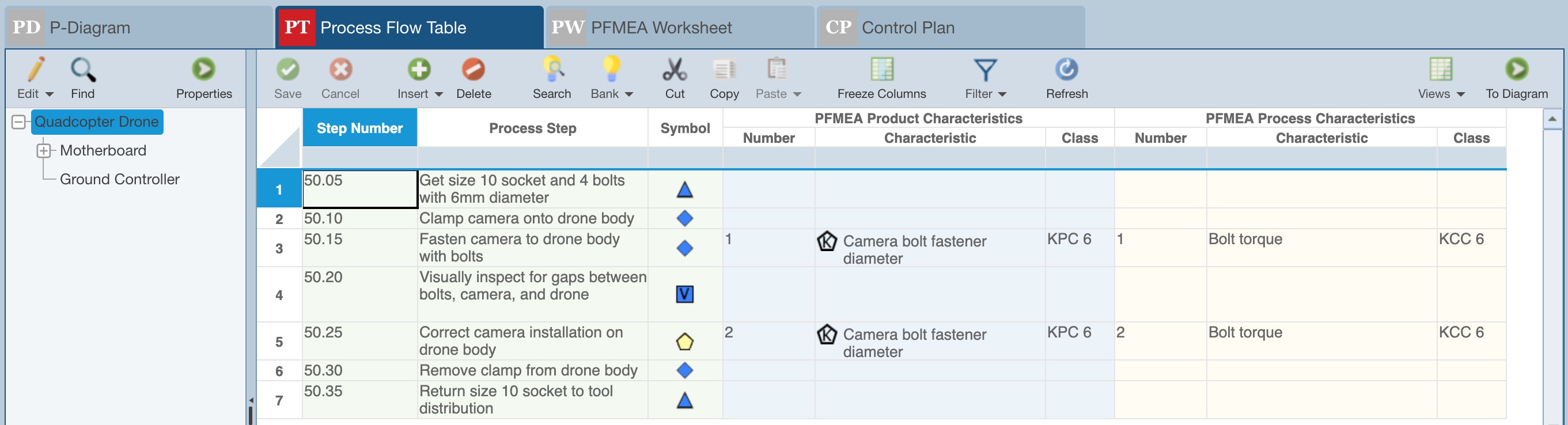
The Process Flow Table view shows a Worksheet, or table, type view of your data.
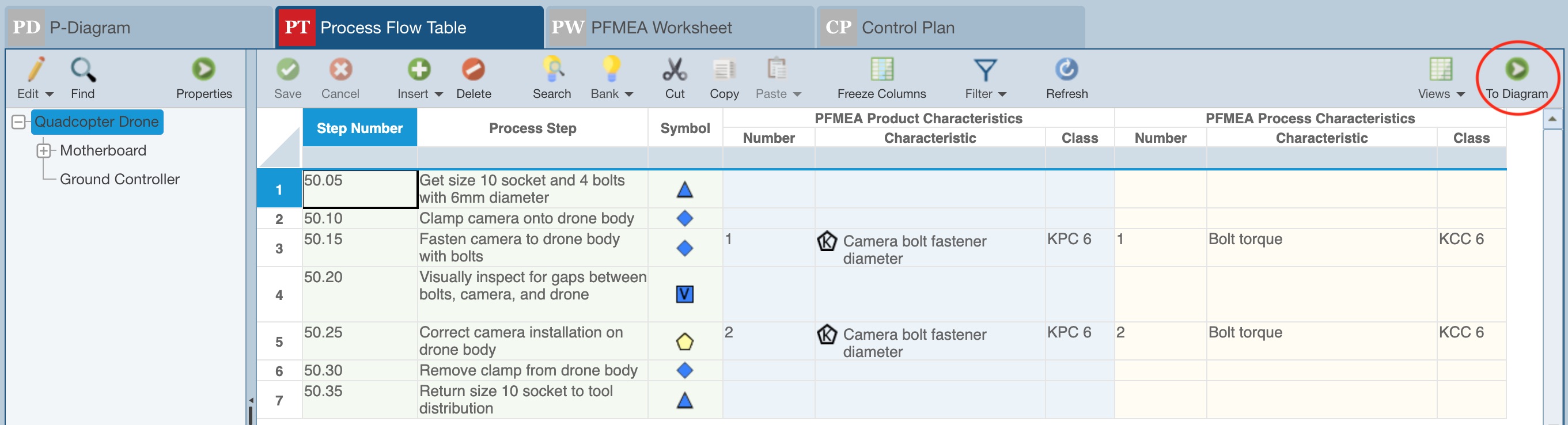
Alternatively, or in addition to the PFT, you can use the Process Flow Diagram (PFD) view to create a graphical representation of your process flow. To view the Process Flow as a Diagram, click the To Diagram button in the upper right of the toolbar.
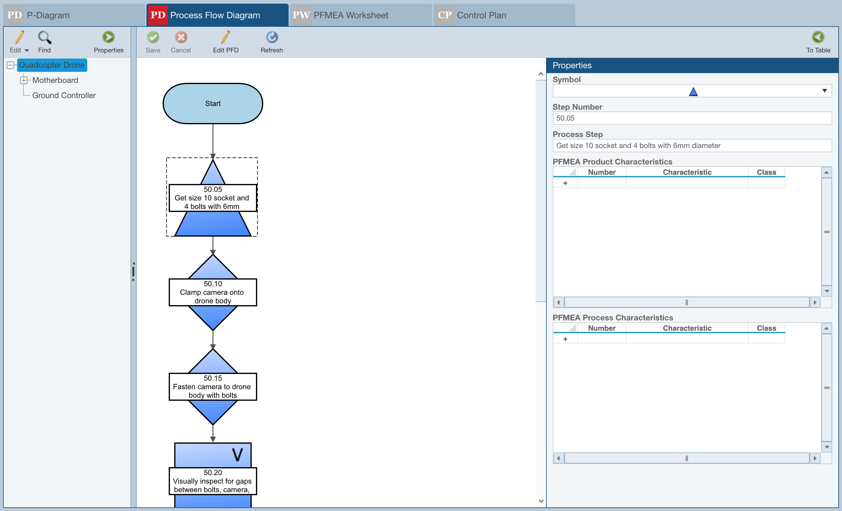
The Process Flow Diagram appears.
Note that your process steps can be entered in either the PFD or PFT. They can also be entered on your PFMEA Worksheet or Control Plan (CP). Wherever you enter process step numbers and descriptions, they are automatically kept in sync across three of the main elements of your PFMEA. In addition to the process steps, the Product and Process Characteristics you have entered in your PFD and/or PFMEA Product Characteristics you have entered in your PFMEA Worksheet appear in your CP automatically. Any new characteristics you enter in your CP will automatically be added to your PFD/PFT.